Understanding the Differences Between Current Transformers and Zero Sequence Current Transformers
Current transformers (CTs) and zero sequence current transformers (ZSCTs) are essential components in electrical systems, playing critical roles in protection and measurement. Understanding the differences between these two types of transformers is crucial for engineers and technicians working in electrical safety and system design.
The Basic Function of Current Transformers
Current transformers are designed to convert high primary currents into manageable secondary currents through a specified transformation ratio. For instance, a CT with a 400/5 ratio can transform an actual current of 400A down to 5A. This functionality is vital for accurate current measurement and system protection, ensuring that monitoring devices and protective relays operate correctly without being exposed to high current levels.
Working Principle of Zero Sequence Current Transformers
Zero sequence current transformers operate on the principles outlined by Kirchhoff’s Current Law, which states that the algebraic sum of the currents entering a node must equal zero under normal conditions. In practical terms, this means that when a system is operating normally without faults, the vector sum of the currents in all phases should also be zero, resulting in no output from the ZSCT.
However, when a ground fault occurs, this balance is disrupted. The fault generates a magnetic flux in the ring core of the ZSCT, inducing a voltage on the secondary side that activates the protection relay. This triggers a trip mechanism, effectively isolating the faulted section to prevent damage and ensure safety.
Functions of Zero Sequence Current Transformers
The primary role of ZSCTs is to enhance system protection by detecting faults, particularly ground faults and leakage currents. When such faults occur, the ZSCT activates, cutting off the power supply to prevent electrical shock hazards and equipment damage. This makes ZSCTs indispensable in systems where ground fault detection is critical for safety and operational integrity.
Usage Conditions for Zero Sequence Current Transformers
Zero sequence current transformers are versatile in their application. They can be installed on individual phases of three-phase lines, passed through all three-phase conductors collectively, or placed on the neutral line. This flexibility allows them to effectively monitor the vector sum of three-phase currents:
- Under Balanced Conditions: When the three-phase load is balanced, the zero sequence current (Io) should ideally be zero, indicating no ground fault or leakage.
- Under Unbalanced Conditions: If the load is unbalanced, Io reflects the net unbalanced current (IN).
- During Ground Faults: In the event of a ground fault in one phase, the ZSCT detects the sum of the unbalanced current and the fault current (Id), providing a clear indication of the fault condition.
Understanding these differences and applications helps in the proper selection and use of CTs and ZSCTs, ensuring that electrical systems are both safe and efficient. The installation of the correct type of CT based on the specific protection needs and the system’s operational characteristics can significantly enhance system reliability and safety.
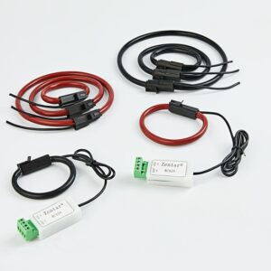
Learn More our series of Zero Sequence Current Transformer (Zero phase current transformer)