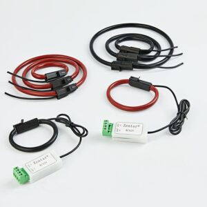
The main uses of RF inductors are diverse, and can be used in various structural features to consider performance testing schemes for special applications. Matching, resonators and choke coils are the main common uses of inductors in RF power circuits. Matching includes removing the characteristic impedance mismatch and minimizing the reflective surface and loss of the middle route of power circuit blocks (such as wireless antennas and radio frequency blocks or high frequency (IF) blocks). Series resonance is used for synthesizers and resonant circuits to adjust the power supply circuit and set the required frequency.
When used as a choke coil, the inductor can be placed in the switching power supply line of the active component, such as a radio frequency block or a high frequency block, in order to better attenuate the high frequency communication current. The reference point three-way allows AC current to reference point active devices, such as diodes. The AC reference point current and the AC/RF data signal are accumulated together and output from the AC+DC output port number.
inductance
RF inductor specifications and models
Inductance is a characteristic of electrical conductors. It can resist the transition of current passing through the conductor. It is the ratio of the induced voltage to the current coefficient of elasticity that causes the induced voltage. The inductance rated current of radio frequency inductors is generally 0.5nH or less, to hundreds of nanohenries. Inductance depends on the structure, transformer core specifications, transformer core raw materials and the number of turns. Inductors can be listed as fixed or variable inductance values.
Alternating current rated current (DCR) is related to resistance measurement, with amperes as the business. DCR specifies the amount of current that the inductance can solve under conditions of heat or saturation. When considering the thermal characteristics of the inductor, this is a key index value. The output power loss increases with the expansion of current and resistance measurement, which will cause the temperature of the inductor to rise. The rated value temperature of an inductor is generally a special operating temperature, and the temperature rise is because the current depends on the inductor. For example, if the rated operating temperature is 125°C, the maximum temperature of a component that is increased by 15°C due to the full-rated current (Irms or Idc) is approximately 140°C.
The saturation current is a DC power source, which reduces the inductance to a certain value. The decrease in inductance is due to the fact that the transformer bobbin only includes a certain amount of magnetic flux density. The saturation current is related to the magnetic energy of the inductor. DCR describes the larger direct current that the inductor can be based on, and it is related to the physical characteristics.
Self-resonant frequency (SRF) means that if this frequency is exceeded, the sensor stops working. Generally speaking, because of the harm of parasitic capacitance, the greater the inductance, the lower the self-series resonance (SRF), and vice versa. The distributed capacitance of the inductor in the middle of the two electrical levels or the middle of the winding conductor turns is low, and the inductance of the components and the distributed capacitance at the SRF resonate. In SRF, the inductor is treated as a resistor with characteristic impedance. At higher frequencies, distributed capacitance dominates.
When selecting inductors in high-frequency circuits and control modules, only considering that the required inductance is insufficient; SRF should be at least 10 times higher than the output power. For choke coil applications, SRF is the frequency at which the characteristic impedance achieves the highest value, which provides stronger data signal blockage.
The Q factor is a dimensionless main parameter that describes the underdamped condition of an oscillator or resonator. It is similarly defined as the ratio of the original kinetic energy stored in the resonator to the damaged kinetic energy within one radian of the oscillation period. The Q factor can also be defined as the ratio of the bandwidth between the resonator management center frequency when the drive is oscillated.
The high Q value results in agile network bandwidth, which is critical for the inductor as a part of the LC cell (oscillator) power circuit or in the agile application. High Q can also reduce insertion loss and minimize functional loss. All frequency-related real and imaginary losses are included in the accurate measurement of Q, including the skin effect of inductors, capacitors, conductors [1] and transformer core losses of permanent magnet materials.
How to measure specifications and models
Physics RF inductors are non-ideal components, including internal parasitic resistors, inductors, and capacitors. They are discrete systems and can harm the characteristics. Therefore, they must be measured among various characteristic specifications. such as:
Higher currents must be higher transmission lines, it is in order to better maintain the minimum loss and heating. Although higher transmission lines reduce DCR and increase Q, the cost is higher part specifications and possibly lower SRF. In terms of rated current, wire-wound inductors are better than double-layer inductors of the same specification. For double-layer inductors with the same specifications and inductance, the Q value of wire-wound inductors is much higher.
Ferrite core transformer core inductance with lower coil turns can get higher current capacity and lower DCR. As everyone knows, ferrite cores are likely to cause new restrictions, such as the change of inductance with temperature, the fatter time tolerance, lower Q, and its reduced saturation current rating. The ferrite core inductor with a magnetic structure that is open to the outside world will not saturate even at full rated current.
Selection of RF inductor structure
There are already several manufacturing methods that can alleviate various internal parasitic hazards and improve the characteristics of radio frequency inductors to consider the necessity of special applications.
Porcelain’s key integrated ic inductor is used for agile filtering of radio frequency and microwave heating frequency communication equipment. They provide very high Q values and can reduce the inductance time tolerance to 1%.
The ferrite core or transformer core integrated ic inductor is a wire-wound radio frequency choke coil, used to provide protection and wide-screen band filtering, without the saturation of the transformer core. They provide the largest inductance and the smallest DCR in the environmental evaluation specifications given.
The double-layer integrated IC inductor can provide low DCR, high Q and high temperature operation. The structural ceramic structure can achieve excellent performance at high frequencies, and the double-layer processing technology can provide a universal range of inductance values. Double-layer components can provide a more general inductance range than plastic films or air cores, but they cannot match the inductance range or rated current of the wirewound.
Hollow inductors are wire-wound radio frequency choke coils that provide protection and wide-screen band filtering without the need for transformer core saturation. They provide the largest inductance and the smallest DCR in the environmental evaluation specifications given.
Tapered and wide-screen tape inductors have high characteristic impedance over the wide bandwidth of the broadband network. Cone inductors are suitable for ultra-wideband reference point tee up to 100GHz. In the widescreen band reference point application, a single cone inductor can replace several cascaded agile inductors.
Broadband network cone-shaped RF inductors are suitable for applications ranging from test equipment to microwave heating circuit principles. This widescreen inductor works well in biased tee tubes, and can be used for communication platforms and 100GHz radio frequency detection settings
RFID and NFC transmitter sensors are professional equipment that provide high sensitivity and long loading spacing in the transmitter identification and NFC/RFID wireless antenna. They can improve the application, such as the requirement of tire pressure testing with excellent performance in the harsh natural environment of machinery and equipment and the high-temperature actual operation natural environment.
Inductors are a key component in the radio frequency/microwave heating data signal chain. It may be difficult to categorize them. It is necessary to understand various characteristics. Once a standard is established, it is necessary to categorize many structural options before reaching the best components for a particular application.
The skin effect generally refers to the skin effect. When there is an alternating current or alternating magnetic field in a conductor, the current inside the conductor is unevenly distributed, and the current is concentrated in the “skin” part of the conductor. In other words, the current is concentrated in the chromatogram on the surface of the conductor, the closer it is to the surface of the conductor, The higher the relative current density, the smaller the current inside the conductor.


