
As the demand for accurate, non-intrusive current measurement continues to grow in power electronics, EV charging, and industrial automation.
Rogowski coils have become increasingly popular due to their flexibility, safety, and high linearity.
However, for many engineers or procurement professionals unfamiliar with this technology, reading a Rogowski coil datasheet can be confusing.
In this article, we’ll walk you through the most critical parameters in a Rogowski coil specification sheet—what they mean and why they matter for your application.
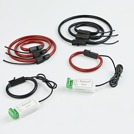
Let take an example of one of ZTC made Rogowski Coils named RC601V830
Rogo coils Parameters
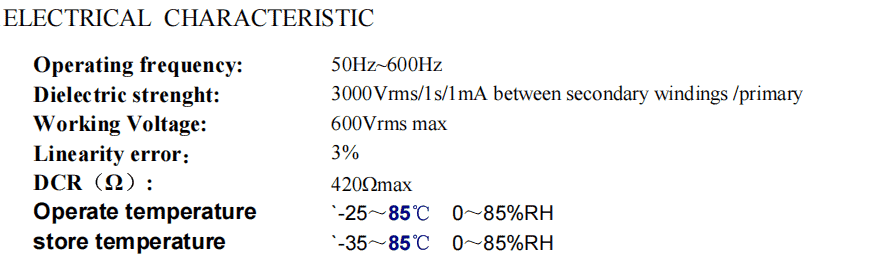
1. Operating Frequency: 50Hz ~ 600Hz
This defines the frequency range within which the Rogowski coil can operate effectively. The typical application range covers:
50/60Hz for power grid monitoring and metering
Up to 600Hz for detecting harmonic distortion or fast-switching transients in industrial systems
Why it matters: Choosing a coil that operates within your system’s frequency ensures accurate signal transformation. Using a coil outside its specified range can lead to distortion or loss of fidelity in current measurement.
2. Dielectric Strength: 3000Vrms / 1s / 1mA
This parameter indicates the electrical insulation strength between the coil’s secondary windings and the primary conductor.
Why it matters: It reflects the product’s ability to withstand high voltage transients and maintain electrical isolation, which is critical for safety, especially in high-voltage environments such as electric vehicle chargers or industrial drives.
3. Working Voltage: 600Vrms Max
This is the maximum continuous voltage the coil can be exposed to in operation.
Why it matters: It ensures the sensor’s insulation system is robust enough for your application’s voltage level. Exceeding this may lead to insulation breakdown or safety risks.
4. Linearity Error: ≤ 3%
Linearity error measures how consistently the coil’s output follows the input current across its range.
Why it matters: Low linearity error means better accuracy. A 3% or less deviation is generally acceptable in energy monitoring or protective relaying, ensuring reliable measurement without costly signal distortion.
5. DCR (DC Resistance): ≤ 420Ω
DCR indicates the coil’s resistance when a direct current is applied to the windings.
Why it matters: A lower DCR can minimize signal loss and improve efficiency, particularly in circuits with sensitive amplification or long-distance signal transmission.
6. Operating Temperature: -25℃ ~ +85℃ / Humidity: 0 ~ 85% RH
The temperature and humidity range defines the environmental conditions in which the Rogowski coil can function reliably.
Why it matters: These values indicate ruggedness. Whether you’re installing the coil in an outdoor cabinet, inside an EV charger, or near a high-temperature power device, these specs ensure stable performance without degradation.
7. Storage Temperature: -35℃ ~ +85℃
Indicates the environmental limits when the coil is not in operation.
Why it matters: Proper storage conditions are essential to maintain long-term product integrity before installation or during transportation.
Selecting the Right Rogowski Coil
Understanding these parameters is critical for engineers selecting the right Rogowski coil for current sensing in applications such as:
Residual current detection (Type B)
EV charging systems
Smart power meters
Industrial motor control
At Xiamen ZTC Technology, we specialize in manufacturing high-performance Rogowski coils tailored to your needs. If you have a specific technical requirement or need assistance in selecting the right sensor for your application, feel free to contact our engineering team for expert support.