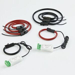
First of all, the current transformer is an instrument and equipment that converts a large current into a small current on the secondary side according to the principle of electromagnetic induction. The current transformer is composed of a closed iron core and windings. Its primary winding has very few turns and is stringed in the path of the current that must be measured. Then today I will give you some small knowledge about current transformers.
-
The error of current transformer
Under normal circumstances, the current transformer secondary current Is=Ip/n, there will be no error. But in fact, no matter in the amplitude (considering the transformation ratio conversion) and the viewing angle, there are differences between the primary and secondary currents. The specific current injected into the secondary load of the voltage transformer Is=Ip/n-ie, where e is the excitation current, that is, the working current required to create the electromagnetic field. Then there will be an error in the current amplitude. When everything is in normal operation, the excitation impedance is quite large and the excitation current is not large, so the error is not quite large and can often be ignored. However, when the voltage transformer is saturated, the excitation impedance will decrease, and the excitation current will expand, which will increase the error. Fully consider that the excitation impedance is generally solved as an inductance characteristic, and the secondary load is generally an impedance characteristic. Therefore, under the effect of the secondary magnetic induction potential difference Es, Is and Ie are not the same position, which leads to the primary current Ip=s ten e and The secondary current Is has a viewing angle error, and the angle error is related to the secondary load characteristics.
-
Error analysis and calculation of current transformer
After we understand that the key to the error of the current transformer is caused by the excitation current Ie, we will check whether the error of the applied current transformer meets the regulations based on the specific operating conditions. The error of voltage transformer includes viewing angle error and amplitude error. As far as the technical field of relay protection is concerned, the accurate measurement of the angle of view error is excessively complicated and the error rarely exceeds the standard under specific circumstances. People are more concerned about the amplitude error. People generally stipulate that when the primary current Ip is equivalent to the short-circuit fault current at the maintenance installation place, the amplitude error is not more than 10%. This is also the rule in the 10% error analysis that people usually say.
According to general circuit principles, people know that in order to consider the 10% error (Ie is not greater than 10% of Ip/kn), it is necessary to ensure that the excitation impedance e is greater than 9 times the total load impedance of the secondary circuit (Xct+rct+zb ). Therefore, in order to carry out the 10% error analysis, people must understand the short-circuit fault current at the maintenance installation, the voltage transformer excitation impedance value that matches this current, and the total load impedance of the secondary loop of the current transformer.


