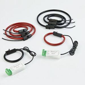
The zero phase current transformer is a line fault current monitor. Generally, there is only one iron core and secondary winding. When using, the primary three core cable is passed through the iron core window of the transformer, and the secondary wire is connected to a special relay, and then the output terminal of the relay is connected to a signal device or an alarm system.
Under normal circumstances, the three phase currents in the primary circuit are basically balanced, and the resulting combined magnetic flux is also close to zero. No current is induced in the secondary winding of the transformer.
When a single phase grounding fault occurs in the primary line, an unbalanced current (meaning zero phase current) is generated in the primary circuit, and a tiny current is induced in the secondary winding to make The relay operates and a signal is generated. The current that makes the relay act is very small (mA level), which is called the sensitivity of the secondary current or zero phase current transformer (it can also be expressed by a minimum operating current), which is the main action index.
The current transformer located inside the switch in the 10kV feeder switchgear is generally divided into two phase or three phase depending on the wiring method. The current transformer consists of primary windings (L1, L2), secondary windings, iron cores and cast with silicone rubber.
The difference between zero sequence current transformer and current transformer
The basic principle is the same as that of ordinary transformers. The main differences are:
- The use methods are different. The zero phase current transformer is used to detect the zero phase current. Generally, all three live wires are passed through the inner hole of the transformer, and the vector sum of the three phase current is measured, that is, the zero-sequence current.
- The characteristics of zero phase current determine that under normal circumstances, the primary current of the zero phase transformer is very small, but under abnormal conditions, the zero-sequence current will also be very large. This requires a wide measurement range of the zero phase current transformer. Therefore, the zero phase transformer usually allows a larger multiple of overload, and the overload capacity is reflected by the “accurate limit coefficient”.
- Since the zero phase transformer usually passes through three live wires, under the same primary current, the inner hole of the zero phase transformer is larger. “Inner hole diameter” is an important index of zero phase transformer, which should be indicated when ordering.