Most technicians are very familiar with the GFCI sensor for ground fault current detection.The detection principle is as follows:
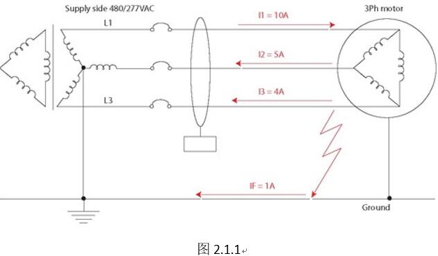
In a three-phase system, a chip-type RCMU (leakage current monitoring unit) is placed on the bus. The most important thing is that all three buses pass through the middle hole of the RCMU randomly. The illustrated system does not have a neutral line and is a three-phase three-wire AC system. If it is a three-phase four-wire system, if the current does not run on the center line, the center line does not have to pass through the RCMU. Assuming a 10A load connected to a 480/277vac system, the RCMU will measure it simultaneously. According to Kirchhoff’s law, the incoming and outgoing currents will cancel each other out. The current vector sum of the three busbars should be zero. It can be seen from the figure that without considering the direction: 10A-5A-4A = 1A, that is, the leakage current value on the system line is 1A. RCMU’s chip-based design principle is different from passive transformers in that it can detect different leakage components and belongs to Type-B RCMU.
Having said that, briefly review the type of leakage current type.
1) AC type leakage protector:
The AC type leakage protector is designed for the power frequency sinusoidal leakage current, and can reliably protect the sinusoidal leakage current that is suddenly applied and slowly rising.
2) Type A leakage protector:
In addition to the reliable protection of the sinusoidal leakage signal, the A-type leakage protector can also reliably protect the leakage signal containing the pulsating DC component.
3) Type B leakage protector:
B type leakage protector can reliably protect sinusoidal AC signal, pulsating DC signal and smooth signal
3. Application of leakage current protection in electric vehicle charging piles
1. There are 4 modes of electric vehicle charging piles:
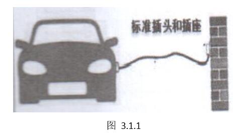
1) Mode 1:
• Charging is not controlled
• Power interface: ordinary power socket
• Charging interface: dedicated charging interface
•In≤8A;Un:AC 230,400V
•The conductor on the power supply side provides phase, neutral and ground protection
Electrical safety depends on the safety protection of the power supply grid, and the safety is poor, and it is eliminated in the GB/T 18487.1-2 standard
2) Mode 2:
• Charging is not controlled
• Power interface: ordinary power socket
• Charging interface: dedicated charging interface
•In<16A;Un:AC 230
• Power and current: 2Kw (1.8Kw) 8A 1Ph; 3.3Kw (2.8Kw) 13A 1Ph
• Earth protection, over current (over temperature)
•The conductor on the power supply side provides phase, neutral and ground protection
• With protection device / control function
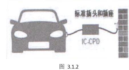
Electrical safety depends on the basic safety protection of the power supply grid and the protection of IC-CPD
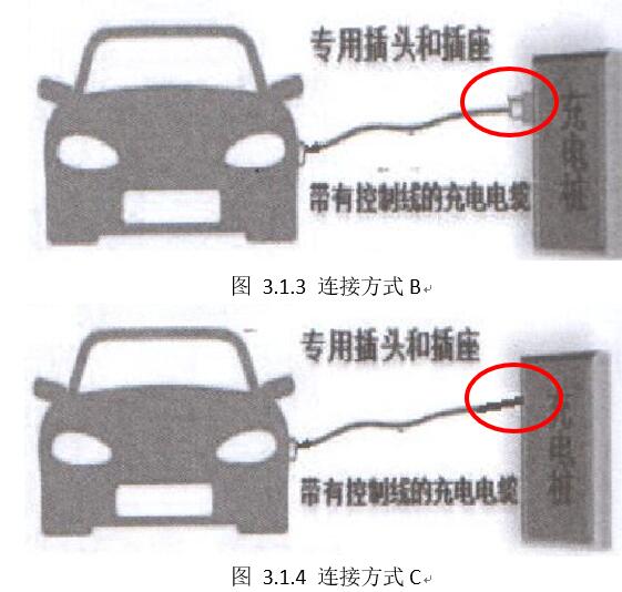
3) Mode three:
• Input power: low voltage AC
• Charging interface: dedicated charging interface
•In<63A;Un:AC 230,400V
• Power and current 3.3Kw 16A 1Ph; 7Kw 32A 1Ph; 40Kw 63A 3Ph
• Earth protection over current
•The conductor on the power supply side provides phase, neutral and ground protection
• With protection device/control function, the plug is integrated on the charging pile
Electrical safety is based on special charging piles and guided detection between piles and vehicles
4) Mode 4:
Control charging
•Stand-type charger
• Power 15KW, 30KW, 45KW, 180KW, 240KW, 360KW (charging voltage and current depend on module size)
• The function with monitoring and protection device/control is integrated on the pile
• Built-in charging station charging cable
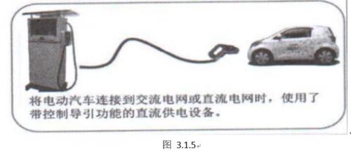
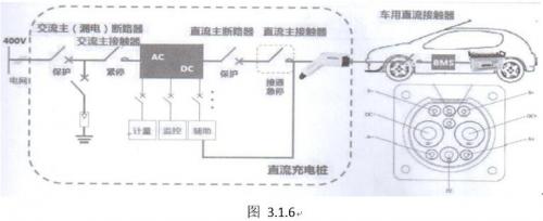
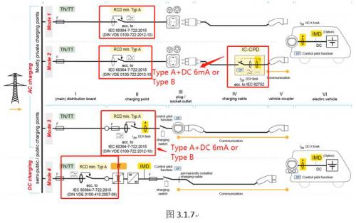
Figure 3.1.7 Leakage current protection points in the four charging modes: