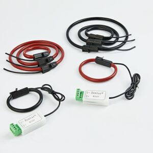
The current transformer is an instrument and equipment that converts a large current on the primary side into a small current on the secondary side for accurate measurement according to the basic principle of the magnetic effect of current. It is mainly composed of a closed iron core and windings.
Its primary side winding has a very small number of turns, which are connected in series in the route of the amount of current that must be accurately measured; the secondary side winding has a relatively large number of turns, which are connected in series in the detection instrument and maintenance control loop. The secondary side of the current transformer cannot be opened.
The correct method of winding and the calculation of the number of coil turns
We should first determine the magnification of the transformer according to the size of the load, and then pass the primary wire through the management center of the transformer as required. Note that the coil wound on the outer ring should not be used as the number of turns, and the current transformer should be passed through. The number of turns in the coil is standard.
For example, the current transformer with the maximum conversion ratio of 150/5 has a maximum rated current of 150A. If it needs to be used as a 50/5 transformer, the transmission line should be wound with 150/50=3 turns, that is, the inner The circle is wound around 3 turns, and the outer ring is only 2 turns at this time. That is to say, after seeing through a few turns, it is enough to count the clear circle holes.
Calculation of Transforming Ratio and Coil Turns
Some current transformers have lost their factory nameplates in the application. When the customer’s load changes and the transformation ratio of the current transformers needs to be converted, the transformer should be calibrated first, and the maximum primary rated current of the transformers should be clarified. Calculation of transformation ratio and number of coil turns.
For example, if a current transformer with a maximum primary rated current of 150A is to be used as a 50/5 transformer, the formula is converted to:
The number of turns of the primary core coil = the current maximum primary rated current of the current transformer / the maximum primary rated current of the transformer to be converted
The number of turns of a core coil = 150/50 = 3 turns
That is, it is converted into a 50/5 current transformer, and the number of turns of the core coil is 3 turns at a time. Similarly, if the transformation ratio of the original current transformer is 50/5, and the number of turns of the core coil is 3 turns, when it is used as a 75/5 transformer, we should first measure the maximum rated current in the case of a single turn : Maximum primary rated current = primary current in the original application×number of turns of the original core through coil = 50×3 = 150A.
The number of turns of the grommet coil after conversion to 75/5 is 150/75=2 turns. That is, when a 50/5 current transformer with 3 turns of the original through-core coil is converted into a 75/5 current transformer, the strain on the number of turns of the through-core coil is 2 turns.
Another example is the 50/5 current transformer with 4 turns of the original through-core coil, which needs to be changed into a 75/5 current transformer application. The number of turns of the core-piercing coil should be 200/75≈2.66 turns. In the actual core-piercing, the number of turns of the winding coil is only an integer, either 2 turns or 3 turns. Whether we wear 2 turns or 3 turns, there will be deviations in accurate measurement.
Therefore, when we do not know the maximum primary rated current of the current transformer, it is not possible to change the ratio at will, otherwise it is likely to cause measurement deviations.


