Understanding the Differences Between Current Transformers and Voltage Transformers
Electric power systems rely on various types of transformers to ensure accurate measurement and safe operation. Two fundamental types are current transformers and voltage transformers, each serving unique functions with distinct structural features and operational principles.
The distinction between current and voltage transformers lies in their connection, function, and operation within power circuits. Current transformers are integrated in series, focusing on current measurement and ensuring safety by keeping the secondary winding closed. Voltage transformers, however, are connected in parallel and focus on voltage measurement, allowing their secondary winding to be open without risk. Understanding these differences is crucial for professionals in power engineering to select and implement the appropriate transformer type for specific applications.
Structural Differences
Current Transformers:
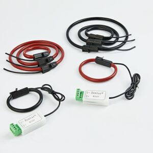
- Primary Winding: Current transformers typically have one or a few turns of thick wire in their primary winding. They are connected in series with the load to measure current directly from the power circuit.
- Secondary Winding: This winding usually has more turns and is specifically designed so that it must not be opened under operation due to the risk of high voltage spikes which can be dangerous.
Voltage Transformers:
- Primary Winding: In contrast, voltage transformers have many turns in their primary winding and are connected in parallel with the high-voltage power grid to step down the voltage.
- Secondary Winding: The secondary winding has fewer turns and is connected to devices such as voltmeters or power factor meters, and can be safely opened without the risk of generating hazardous voltages.
Working Principles
Operational States:
- Current Transformers:
- Operate with a secondary circuit that must always be closed as an open secondary can lead to dangerous voltage levels due to the transformer’s design to handle high current levels.
- The primary internal impedance is very high, functioning effectively as an infinite-resistance current source.
- Normal operation sees low magnetic flux density, but this can increase significantly during a primary side short-circuit fault, potentially exceeding saturation levels.
- Voltage Transformers:
- Their secondary circuit can safely be opened, but must not be short-circuited, to avoid faults.
- They typically have a low or negligible primary internal characteristic impedance, acting as a voltage source.
- Magnetic flux density normally operates close to the saturation threshold but decreases during faults.
Functional Differences
Current Transformers:
- The primary role is to ensure the stable and safe operation of the power engineering system by monitoring and accurately measuring the operational conditions of electrical equipment. As high-voltage equipment cannot be directly connected to precision measurement or relay protection devices, current transformers convert high primary currents to a smaller, manageable current for these devices.
Voltage Transformers:
- These transformers are tasked with converting high primary voltages to a regulated, lower secondary working voltage (typically 100V or less), providing a safe and stable voltage for relay protection, metering equipment, and control panels.